Locations Throughout the Country
ISO 9001:2015
Tel: (877) 740-2007
Fax: (800) 453-9683
Email: sales@askmonroe.com
Website: monroeengineering.com

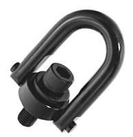
HOIST RING MATERIAL: Alloy steel (Certified heat treatment). Black Oxide . SAFETY FACTOR: 5:1
RANGE OF MOVEMENT: 360° Swivel, 180° Pivot
INSTALLATION: Tap work piece for hoist ring screw with axis vertical to mounting surface. Work surface should be flat and smooth to provide full 360° flush seating for the bushing flange. (SAFETY NOTE: Some loosening may develop after prolonged service in a permanent installation. It is advisable to periodically re-tighten the mounting screw to maintain the specified torque value.) The use of free fit spacers between the bushing flange and mounting surface is not recommended as this will reduce the safe load rating on angularly applied loads. Hoist Ring must be free to swivel 360° and pivot 180° at all times.

| Items |
 MA-23050SE Safety Engineered Hoist Rings - Inch |
 MA-23051SE Safety Engineered Hoist Rings - Inch |
 MA-23052SE Safety Engineered Hoist Rings - Inch |
 MA-23053SE Safety Engineered Hoist Rings - Inch |
 MA-23301SE Safety Engineered Hoist Rings - Inch |
|||||
| Weight | N/A 5.00 oz | N/A 5.00 oz | N/A 5.00 oz | N/A 5.00 oz | N/A 1.00 lb | |||||
| Material | N/A Alloy Steel | |||||||||
| Finish | N/A Black Oxide | |||||||||
| D - Diameter | N/A 0.38 in | N/A 0.38 in | N/A 0.38 in | N/A 0.38 in | N/A 0.50 in | |||||
| Safety Factor (Min.) | N/A 5:1 | |||||||||
| Pivot | N/A 180 º | |||||||||
| Swivel | N/A 360 º | |||||||||
| Weight | N/A | |||||||||
| Torque | N/A 5.00 lb·ft | N/A 7.00 lb·ft | N/A 7.00 lb·ft | N/A 12.00 lb·ft | N/A 28.00 lb·ft | |||||
| A - Radius | N/A 0.43 in | N/A 0.43 in | N/A 0.43 in | N/A 0.43 in | N/A 0.70 in | |||||
| B - Base Height | N/A 0.71 in | N/A 0.71 in | N/A 0.71 in | N/A 0.71 in | N/A 0.93 in | |||||
| C - Ring Width | N/A 1.61 in | N/A 1.61 in | N/A 1.61 in | N/A 1.61 in | N/A 2.40 in | |||||
| E - Thread Length | N/A 0.54 in | N/A 0.29 in | N/A 0.54 in | N/A 0.54 in | N/A 1.07 in | |||||
| Thread Length Tolerance | N/A ± 0.060 in | |||||||||
| F - Height | N/A 2.67 in | N/A 2.67 in | N/A 2.67 in | N/A 2.67 in | N/A 3.77 in | |||||
| Height Tolerance | N/A ± 0.060 in | |||||||||
| G - Thread Size | N/A 1/4-20 | N/A 5/16-18 | N/A 5/16-18 | N/A 3/8-16 | N/A 1/2-13 | |||||
| H - Inside Clearance | N/A 1.33 in | N/A 1.27 in | N/A 1.27 in | N/A 1.21 in | N/A 1.84 in | |||||
| I - Overall Width | N/A 1.84 in | N/A 1.84 in | N/A 1.84 in | N/A 1.84 in | N/A 2.58 in | |||||
| Overall Width Tolerance | N/A ± 0.060 in | |||||||||
| J - Base Width | N/A 0.75 in | N/A 0.75 in | N/A 0.75 in | N/A 0.75 in | N/A 1.25 in | |||||
| PS - Load Rated | N/A 550 Pounds (249 kg) | N/A 800 Pounds (363 kg) | N/A 800 Pounds (363 kg) | N/A 1000 Pounds (454 kg) | N/A 2500 Pounds (1134 kg) | |||||
|
|
||||||||||